
Working Model of Valve Timing
Product Code : EL-AELE-10751
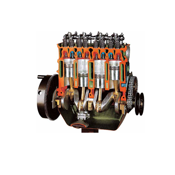
Working Model of Valve Timing (code EL-AELE-10751) is a cut section model of a multi-cylinder engine used to demonstrate valve timing, the timing of the opening and closing of the engine's valves, and to measure and draw the valve-timing diagram. The fully functional engine section has 4 in-line cylinders on the 4 stroke cycle, a belt-driven overhead camshaft, indirect injection with a VE type rotary injection pump and turbo supercharger feeding, all in a mobile powder coated frame of approx. 700 × 700 × 800 mm.
Get a quote: use the Add To Cart enquiry button below, or send your quantity and delivery location through the contact page.
Specifications
| Parameter | Detail |
|---|---|
| Use | Demonstrating valve timing; measuring and drawing the valve-timing diagram |
| Construction | Fully functional cut section system installed in a mobile solid frame |
| Stand | Powder coated metal stand |
| Engine | 4 stroke, 4 in-line cylinders |
| Camshaft | Overhead camshaft (OHC) |
| Distribution | Through a toothed belt |
| Fuel injection | Indirect injection; VE type rotary injection pump |
| Induction | Feeding by turbo supercharger |
| Sectioning | Various parts cross-sectioned to show internal operation |
| Colour coding | Parts, cross-sections, lubricating circuits, fuel system and cooling system painted in different colours |
| Finish | Many parts chromium plated and galvanised |
| Operation | Mechanism operated manually |
| Layout | On base with wheel |
| Dimensions | Approx. 700 × 700 × 800 mm (L × W × H) |
| Weight | Approx. 65 kg |
| Product code | EL-AELE-10751 |
| Manufacturer | Engineering Lab Equipment, Ambala, Haryana, India |
What Is the Working Model of Valve Timing Used For?
Valve timing fixes the crank angles at which the inlet and exhaust valves open and close; in practice the inlet opens slightly before top dead centre and the exhaust closes slightly after it, giving a short overlap that helps the cylinder fill and empty at speed. Turning the engine by hand, students note the crankshaft position at each valve event, read off the angles and plot them as a valve-timing diagram. The sectioned overhead camshaft and toothed belt then show how the belt-driven camshaft sets those events for all 4 cylinders, and why the belt must keep the camshaft in step with the crankshaft.
What to Specify When Ordering
- Quantity — how many valve timing models are needed.
Frequently Asked Questions
What is valve timing?
In a piston engine it is the timing of the opening and closing of the valves; in four-stroke engines it is controlled by the camshaft and is also affected by the adjustment of the valve mechanism.
Can students draw a valve-timing diagram with it?
Yes. Measuring and drawing the valve-timing diagram is one of the listed uses, with the mechanism turned by hand so that each valve event can be found.
Which engine features does the section show?
It shows a four stroke engine with its 4 cylinders in line, a toothed-belt-driven overhead camshaft, indirect injection from a VE type rotary injection pump and turbo supercharger feeding.
How can valve timing be varied in engines?
It can be changed by modifying the camshaft, varied during engine operation by variable valve timing, and is also affected by how the valve mechanism is adjusted.
What frame and stand does it use?
The cut section engine sits in a mobile frame carried on a powder coated metal stand; overall it is about 700 × 700 × 800 mm and approximately 65 kg.
OEM Manufacturer
Buyers of the Working Model of Valve Timing deal directly with its maker, Engineering Lab Equipment (Engineering Labs Equipment Pvt Ltd), whose works are at Plot No. 43, Industrial Park, Sector 2, Growth Center, Saha, District Ambala, Haryana, India. The company designs, makes and tests automobile engineering cut-section models, working models and trainers, supplies engineering colleges, polytechnics, technical training institutes and research laboratories in India and overseas, and builds to institution-specific requirements on request. Tender details are on the Tenders/OEM page.
Related Automobile Engineering Equipment
- Cut Section Model of Four Stroke Petrol Engine — dissectible 160cc, 6 hp overhead-valve petrol engine in section with flywheel, key card and literature.
- Working Model of MPFI Petrol Engine — colour-coded cutaway multi-point injection 4 cylinder petrol engine with 5 speed gearbox and Lambda probe.
- Working Model of Gear Box — colour-coded 4 forward speed gearbox cutaway with diaphragm clutch and turbocharged 4 cylinder engine.
See the full Automobile Engineering Lab Equipment range or all Mechanical Engineering Lab Equipment.
Request a Quote
For this and other automobile engineering lab equipment, schools and colleges can contact Engineering Lab Equipment, a manufacturer, supplier and exporter based in Ambala, India. Quotations are given on request: send how many valve timing models you require and your delivery location through the contact page, or add the Working Model of Valve Timing to the enquiry cart from this page.
Last updated: October 2026


