Computerized Pressure Control Trainer
Product Code : EL-MAILE-10803
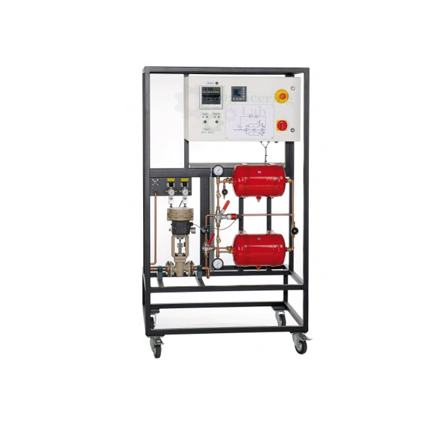
Computerized Pressure Control Trainer (code EL-MAILE-10803) is an air pressure control loop for teaching control engineering, set up as a second-order system of two in-line pressure tanks joined by a flow control valve. Each tank holds 10 L and is rated at 10 bar for an operating pressure of 6 bar; a 0–6 bar sensor reads the pressure in the second tank, and a digital industrial controller drives a pneumatically operated DN15 control valve.
Get a quote: use the Add To Cart enquiry button below, or send your quantity and delivery location through the contact page.
Specifications
| Parameter | Detail |
|---|---|
| Use | Experimental introduction to control engineering, using pressure control as the example |
| Process | 2nd order air pressure system: two in-line pressure tanks interconnected by a flow control valve |
| Disturbance | Additional valve on the second tank allows air tapping to simulate a disturbance variable |
| Controller | Digital industrial controller with freely selectable parameters: P, I, D and all combinations |
| Actuator | Pneumatically operated control valve with standardised current signal input |
| Construction | Components commonly used in industry |
| Pressure tanks | |
| Number | 2 |
| Capacity | 10 L each |
| Pressure | 10 bar |
| Operating pressure | 6 bar |
| Pressure sensor | 0–6 bar, measuring the pressure in the second vessel |
| Pneumatically operated control valve | |
| Connecting flanges | DN15 |
| Kvs | 0.1 m³/h |
| Reference variable | 4–20 mA |
| Stroke | 15 mm |
| Characteristic curve | Equal-percentage |
| Recording and signals | |
| Line recorder | Integrated, 2-channel, 2 × 4–20 mA; plots controlled variable X and manipulating variable Y |
| Recorder feed rate | 0–7200 mm/h, stepped |
| Process variables X, Y | Analogue signals, 4–20 mA, at lab jacks on the switch cabinet for an oscilloscope, flatbed plotter or similar recorder |
| Power and size | |
| Power supply | 230 V, 1 phase, 50 Hz or 60 Hz |
| Dimensions | 1000 × 700 × 1750 mm (L × W × H) |
| Weight | Approx. 110 kg |
| Supply | |
| Product code | EL-MAILE-10803 |
| Manufacturer | Engineering Lab Equipment, Ambala, Haryana, India |
What Is the Computerized Pressure Control Trainer Used For?
Two tanks in series form a second-order process: pressure has to build up in the first vessel before it reaches the second, so the response is delayed and S-shaped, which makes controller tuning more demanding than for a single vessel. Students set the P, I and D terms, let the controller hold the pressure in the second tank through the pneumatic control valve, then bleed air from the extra valve on that tank to act as a disturbance. The sensor signal and the valve command, X and Y, appear on the 2-channel line recorder, or can be fed from the lab jacks to an oscilloscope or flatbed plotter.
What to Specify When Ordering
- Quantity — the number of trainers required.
- Power supply — 230 V single phase at 50 Hz or at 60 Hz.
Frequently Asked Questions
Why does the trainer use two pressure tanks?
The two in-line tanks, joined by a flow control valve, form a second-order system, so the pressure in the second tank follows a change with a delay and gives a more demanding control task than one vessel.
What pressures are the tanks designed for?
Each of the two 10 L tanks is rated at 10 bar, and the system works at an operating pressure of 6 bar, matching the 0–6 bar range of the pressure sensor.
How is a disturbance simulated?
An additional valve on the second tank lets air be tapped off, which lowers the pressure in that vessel and acts as a disturbance variable for the controller to correct.
Which actuator does the controller drive?
It drives a pneumatically operated control valve with DN15 connecting flanges, a 4–20 mA reference variable, Kvs 0.1 m³/h, a 15 mm stroke and an equal-percentage characteristic curve.
How are the controlled and manipulating variables recorded?
Both are plotted on an integrated 2-channel line recorder with a stepped 0–7200 mm/h feed, and both can also be tapped as 4–20 mA analogue signals at the switch-cabinet lab jacks.
How large and heavy is the unit?
The trainer measures 1000 × 700 × 1750 mm (L × W × H), weighs approx. 110 kg and is supplied for 230 V single phase at 50 Hz or 60 Hz.
OEM Manufacturer
The Computerized Pressure Control Trainer is made by Engineering Lab Equipment (Engineering Labs Equipment Pvt Ltd) at its works at Plot No. 43, Industrial Park, Sector 2, Growth Center, Saha, District Ambala, Haryana, India. The company designs, makes and tests measuring instruments and instrumentation trainers for engineering laboratories for engineering colleges, polytechnics, technical training institutes and research laboratories in India and overseas, and can build equipment to an institution's own requirements. Tender and OEM enquiries are handled through the Tenders/OEM page.
Related Measuring Instruments
- Computerized Flow Control Trainer — water flow control loop trainer with electromagnetic flow sensor, motorised control valve and 2-channel line recorder.
- Current to Pressure Measurement Trainer — current to pressure converter trainer for 4 to 20 mA input and 3 to 15 PSI output.
- Digital Wattmeter — 0-6000 W power meter that also reads AC voltage, current and power factor on a backlit dual LCD.
- Load Measurement Trainer — 1 kg compression strain gauge load cell trainer with weights and 3.5 digit kg indicator.
See the full Measurement and Instrumentation Lab Equipment range or all Mechanical Engineering Lab Equipment.
Request a Quote
For this and other measurement and instrumentation lab equipment, schools and colleges can contact Engineering Lab Equipment, a manufacturer, supplier and exporter based in Ambala, India. To ask for a quotation, send the number of trainers and whether the 50 Hz or 60 Hz, 230 V supply version is needed and your delivery location through the contact page, or use the Add To Cart enquiry button on this page.
Last updated: October 2026