Slider Crank Mechanism

Product Code : EL-AMLE-10636
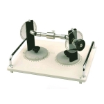
Slider Crank Mechanism (code EL-AMLE-10636) is a bench model of the crank mechanism, the machine element that converts uniform rotation into reciprocating motion or reciprocating motion into rotation. A crank disk drives a connecting rod coupled to a cylinder that stands for the piston; the crank radius has three settings, a screw locks the pivoting cylinder so it can work fixed or oscillating, and the stroke is read on a millimetre steel rule.
Get a quote: use the Add To Cart enquiry button below, or send your quantity and delivery location through the contact page.
Specifications
| Parameter | Detail |
|---|---|
| Use | Demonstrating conversion of uniform rotation into reciprocating motion, or the reverse |
| Components | Crank disk, connecting rod and cylinder |
| Linkage | Connecting rod joined to the crank disk by a crank at one end and to the cylinder at the other |
| Piston | Modelled by the cylinder |
| Crank radius settings | Three, by repositioning the crank on the crank disk |
| Cylinder modes | Fixed or oscillating; pivoting cylinder locked by turning a screw |
| Crank angle | Adjusted with the crank disk; read on an angle scale in the base plate |
| Stroke scale | Millimetre steel ruler attached to the cylinder |
| Base | Base plate with two handles for carrying and stacking |
| Applications shown | Engines, pumps and presses |
| Product code | EL-AMLE-10636 |
| Manufacturer | Engineering Lab Equipment, Ambala, Haryana, India |
What Is the Slider Crank Mechanism Used For?
Engines, pumps and presses all depend on a crank mechanism to link a rotating shaft with a part that moves to and fro. With the cylinder locked by its screw, the student turns the crank disk to a series of angles on the base plate scale and reads the travel on the steel ruler, then frees the cylinder to pivot and repeats the run to see how an oscillating cylinder behaves. Changing between the three crank radii shows the effect of crank length on stroke, and the readings can be plotted as stroke against crank angle.
What to Specify When Ordering
- Quantity — the number of slider crank units required.
Frequently Asked Questions
What is the difference between the fixed and oscillating cylinder settings?
Turning a screw blocks the pivoting cylinder so that the mechanism works with a fixed cylinder; releasing it lets the cylinder oscillate, so both forms of crank mechanism can be shown on one unit.
How many crank radii does the unit offer?
The crank can be repositioned on the crank disk to give three crank radii, letting the effect of crank radius on the stroke be measured.
How are the angle and stroke read?
The crank angle is set with the crank disk and read against a scale built into the base plate, while the stroke is measured on a millimetre steel ruler fixed to the cylinder.
Where are crank mechanisms used?
Crank mechanisms are the functional group in machines that convert uniform rotation into reciprocating motion, or the reverse, and they are used in engines, pumps and presses.
Can several units be stored together?
Yes. Each unit is built on a base plate fitted with a pair of handles, which allows it to be lifted by hand and stacked on top of other units between classes.
OEM Manufacturer
Engineering Lab Equipment (Engineering Labs Equipment Pvt Ltd) builds the Slider Crank Mechanism at its works in Saha, District Ambala, Haryana (Plot No. 43, Industrial Park, Sector 2, Growth Center). Its applied mechanics apparatus for statics, friction, machines and mechanisms go to engineering colleges, polytechnics, technical training institutes and research laboratories in India and abroad, and equipment can be made to an institution's own requirements. For tenders and OEM supply, see the Tenders/OEM page.
Related Applied Mechanics Equipment
- Crank and Connecting Rod Apparatus — crank disk, connecting rod and fixed cylinder unit with three crank radii and millimetre stroke ruler.
- Whitworth Quick Return Apparatus — bench-top Whitworth quick-return crank slider with graduated crank disc, millimetre scale and ball-bearing axles.
- Four Bar Chain Apparatus — four-bar linkage unit with adjustable pivot joints and input and output angle scales on a base plate.
- Geneva Mechanism — slotted star wheel and driving crank model for intermittent rotary motion from a steady input.
See the full Applied Mechanics Lab Equipment range or all Mechanical Engineering Lab Equipment.
Request a Quote
For this and other applied mechanics lab equipment, schools and colleges can contact Engineering Lab Equipment, a manufacturer, supplier and exporter based in Ambala, India. For a price, send the number of slider crank units required and the delivery location through the contact page; the Add To Cart button on this page also adds the Slider Crank Mechanism to an enquiry.
Last updated: October 2026