Subsonic Wind Tunnel

Product Code : EL-FMLE-10681
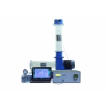
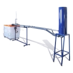
Subsonic Wind Tunnel (code EL-FMLE-10681) is a small, computer-controlled wind tunnel for bench-top aerodynamics and airflow studies, in which a variable speed fan at the discharge end draws air through a clear acrylic working section. The square test section is nominally 150 × 150 mm and 455 mm long, a honeycomb straightener and 9.4:1 contraction condition the inlet flow, and air velocity is variable from 0 to 34 m/s, with a removable base for large models and water or electronic manometer banks.
Get a quote: use the Add To Cart enquiry button below, or send your quantity and delivery location through the contact page.
Specifications
| Parameter | Detail |
|---|---|
| Type | Small wind tunnel for bench top operation, with computer controlled air flow |
| Air drive | Variable speed fan at the discharge end, drawing air through the working section |
| Inlet | Profiled inlet with honeycomb flow straightener and 9.4:1 (nominal) contraction ratio |
| Working section | Square, nominally 150 × 150 mm (6 in nominal), length 455 mm; clear acrylic |
| Air velocity | Variable from 0 to 34 m/s in the test section |
| Model mounting | Model connection points in the sidewall and roof; entire base removable for large or complex models such as the Bernoulli Apparatus, Boundary Layer Plate or models built by the user |
| Manometers | Choice of water or electronic manometer banks; quick release connectors on the manometer tubes |
| Model changing | Quick release fastenings |
| Flow visualisation | Simple flow visualisation technique incorporated |
| Models | Range of models for aerodynamics and air flow studies |
| Power required | 220-240 V, 1 phase, 50 Hz, 10 A |
| Further specifications | |
| Tube length | 320 mm |
| Lift force | 3.4 N |
| Drag force | 3.4 N |
| Inclination | ±45° |
| Inclination | 30° |
| Measurement range | 0-160 mm H2O |
| Channels | 16 channels, 0-178 mm H2O (differential) |
| Chord length | 61.5 mm |
| Thickness | 9.2 mm |
| Cylinder diameter | 30 mm |
| Tapping spacing | 20° |
| Throat width | 100 mm |
| Upstream/downstream width | 150 mm |
| Equatorial diameters | |
| Large models | 50 mm |
| Golf ball and small sphere | 43 mm |
| Dimensions and weight | |
| L × W × H | 2200 × 600 × 700 mm |
| Weight | 220 kg |
| Supply | |
| Product code | EL-FMLE-10681 |
| Manufacturer | Engineering Lab Equipment, Ambala, Haryana, India |
What Is the Subsonic Wind Tunnel Used For?
A wind tunnel moves air past a fixed model so that the forces and pressures on it can be measured as though the model were moving through still air. Students mount a model through the sidewall, roof or removable base, set the air velocity from the computer, and read pressures on the water or electronic manometer bank as the speed or the model inclination is changed. The Bernoulli Apparatus and Boundary Layer Plate fit through the removable base for those studies, and the flow visualisation technique shows the airflow pattern around each model.
What to Specify When Ordering
- Quantity — the number of wind tunnels required.
- Manometer bank — a water or an electronic manometer bank.
Frequently Asked Questions
What air speeds can the tunnel reach?
Air velocity in the test section is variable from 0 to 34 m/s, set by the computer-controlled variable speed fan at the discharge end of the tunnel.
What size is the working section?
The square test section is nominally 150 × 150 mm (6 in nominal) and 455 mm long, made of clear acrylic so that the models under test can be seen.
How is a steady airflow obtained?
A honeycomb flow straightener at the inlet and a profiled inlet with a 9.4:1 nominal contraction ratio give well-developed airflow through the working section.
How are larger models fitted?
The entire base of the working section is removable, so large or complex models such as the Bernoulli Apparatus or Boundary Layer Plate, or models built by the user, can be inserted.
Which manometers can be used?
A water or an electronic manometer bank can be chosen, and the manometer tubes and the model fastenings both use quick release connections.
What power supply does it need?
It runs on 220-240 V, single phase, 50 Hz, 10 A, and the complete tunnel measures 2200 × 600 × 700 mm and weighs 220 kg.
OEM Manufacturer
Engineering Lab Equipment (Engineering Labs Equipment Pvt Ltd) builds the Subsonic Wind Tunnel at its works in Saha, District Ambala, Haryana (Plot No. 43, Industrial Park, Sector 2, Growth Center). Its fluid mechanics apparatus for flow measurement, pipe friction, pumps and hydrostatics go to engineering colleges, polytechnics, technical training institutes and research laboratories in India and abroad, and equipment can be made to an institution's own requirements. For tenders and OEM supply, see the Tenders/OEM page.
Related Fluid Mechanics Equipment
- Centrifugal Fan Demonstration Unit — radial fan rig with forward and backward curved rotors, intake nozzle flow measurement and USB data link.
- Compressible Flow Unit — variable-speed radial fan unit with transparent nozzles, pipe sections and orifice for subsonic and transonic air flow.
- Pitot Tube Apparatus — traversing Pitot static tube in a 32 mm transparent pipe with pressurised water manometer for velocity profiles.
See the full Fluid Mechanics Lab Equipment range or all Mechanical Engineering Lab Equipment.
Request a Quote
For this and other fluid mechanics lab equipment, schools and colleges can contact Engineering Lab Equipment, a manufacturer, supplier and exporter based in Ambala, India. For a price, send the number of wind tunnels and the type of manometer bank, water or electronic and the delivery location through the contact page; the Add To Cart button on this page also adds the Subsonic Wind Tunnel to an enquiry.
Last updated: October 2026